Use the Aligner Tool
The Aligner Tool is one of the most powerful features on the OV80i. It uses edge-based template matching to track your part as it moves, rotates, or shifts between captures. When configured correctly, your Regions of Interest (ROIs) follow the part dynamically, so every inspection crops exactly the right area regardless of how the part is presented. This guide walks you through every feature of the Aligner, explains what each setting does, and shares expert tips that will save you hours of troubleshooting.
The OV80i camera setup follows a strict waterfall process. The Aligner sits at Step 2, after Image Setup and before ROI configuration. If you change anything upstream of the Aligner (lens, lighting, lens distortion correction, camera position), you must recapture your template image and redo alignment. Skipping this will cause subtle, hard-to-diagnose failures downstream.
What the Aligner Actually Does
Every time the camera captures an image, the Aligner runs before any AI inspection happens. It:
- Scans the new image for edge patterns that match the template you defined
- Calculates the offset — how far the part has shifted in X, Y, rotation, and optionally scale
- Moves all your ROIs to match the detected part position
- Reports a confidence score indicating how certain it is about the match
If the confidence score falls below your threshold, the Aligner reports a failure and you can choose to skip inspection or flag the capture as a reject.
The result: you can use smaller, tighter ROIs because they don't need a massive safety margin to account for part movement. Smaller ROIs mean better signal-to-noise ratio, which means the AI needs less training data and produces more accurate results.
The Aligner is 2D only. It works in the plane orthogonal to the camera. It handles translation (X/Y shift), rotation, and minor scale changes (±10%). It does not handle warped parts, bent parts, or 3D perspective transformations. If your part has significant 3D variation, skip the Aligner and use a segmenter with location-invariant properties instead.
Prerequisites
Before configuring the Aligner, make sure you have completed:
- Physical image setup — stable mounting, correct lens, uniform lighting
- Lens distortion correction — set this in Image Settings before capturing a template
- A well-framed part — the part should fill the frame as much as possible to maximize pixel resolution
The Aligner Page at a Glance
Open your recipe in the Recipe Editor and click "Template Image and Alignment" in the left navigation menu.
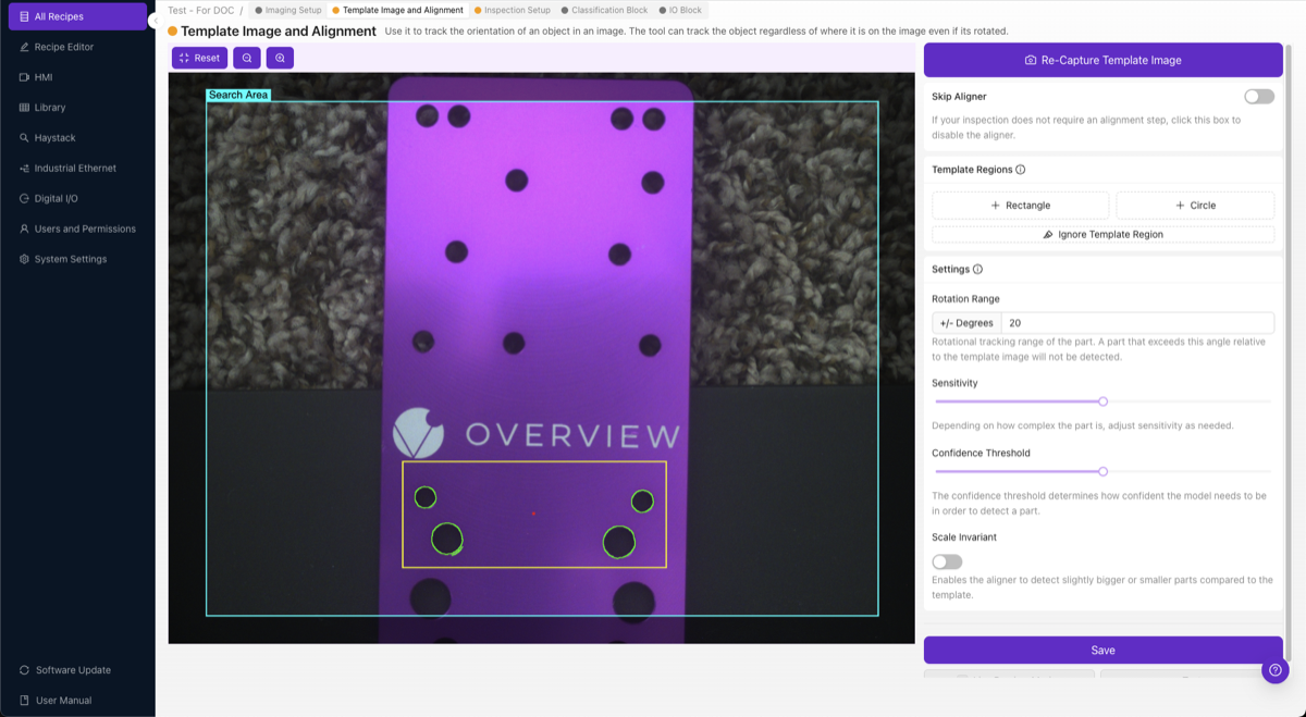
The page has two main areas:
- Left: Image Preview — shows your template image with Template Regions drawn on top. Edge highlights appear inside the regions (green = good edges detected, red = insufficient edges).
- Right: Settings Panel — contains all the controls: Skip Aligner toggle, Template Regions tools, Rotation Range, Sensitivity, Confidence Threshold, Scale Invariant, and the Save button.
At the top you'll see the Re-Capture Template Image button to retake your template, and toggle buttons for Snap (snap mode) and Live (Live Preview Mode).
Step 1: Capture a Template Image
The template image is the reference photo the Aligner uses to find your part. Place a good example part in the camera's field of view and click Re-Capture Template Image.
Your template part should be:
- Well-lit with clear, sharp edges and uniform lighting with no harsh shadows
- Clean without debris, oil, or contamination on the surfaces
- Representative of a normal, non-defective part
- Positioned roughly where parts will typically appear during production
Do not use a defective part as your template. The Aligner matches edge patterns from this image, so any anomalies on the template part become part of the pattern the system expects to see on every part.
After capturing, the preview pane switches from live camera to the static template image. You'll work on this template image to define your regions.
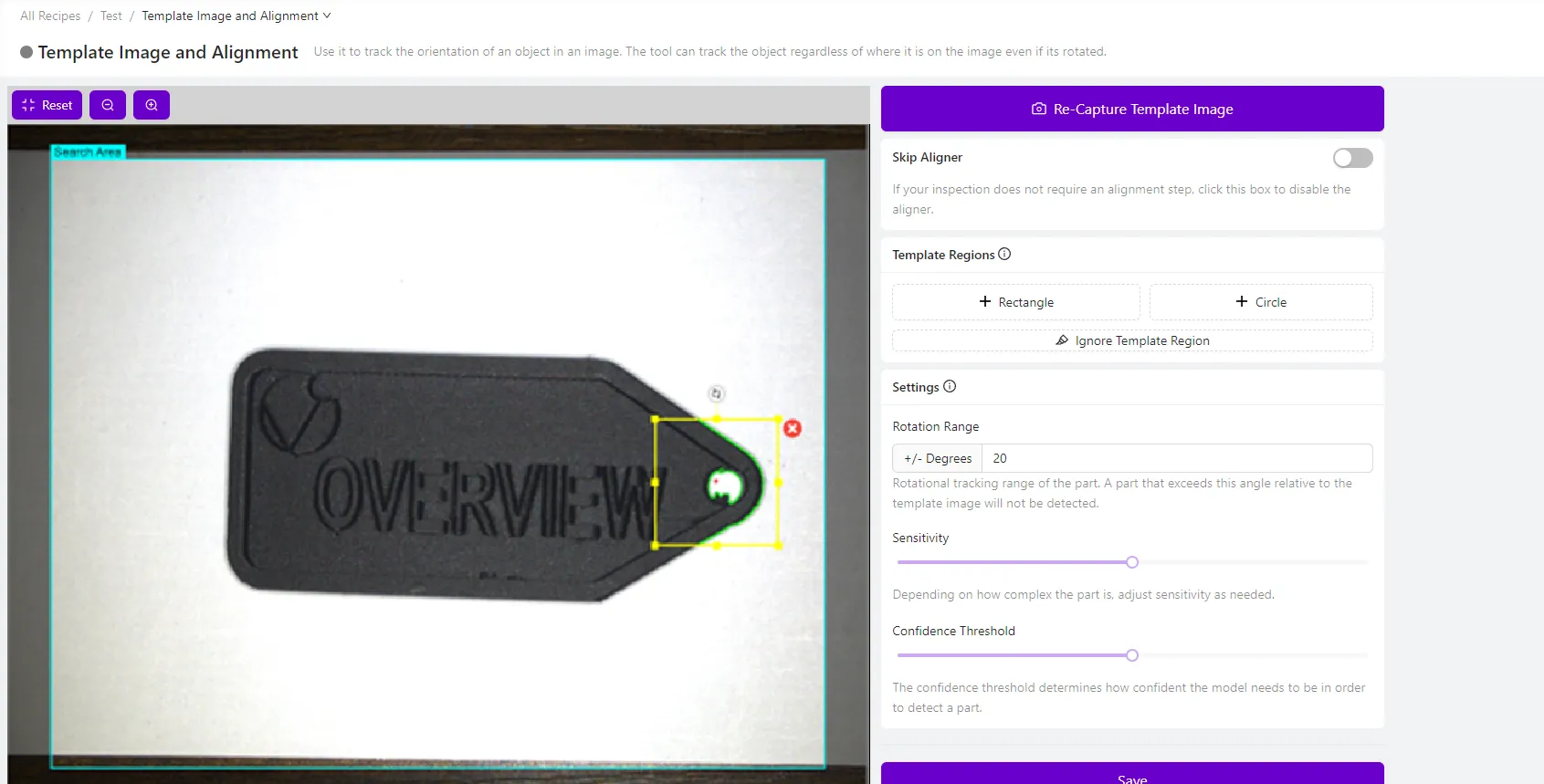
Step 2: Add Template Regions
Template Regions tell the Aligner where to look for edge patterns on the template image. You are drawing boxes (or circles) around distinctive features that the Aligner will use as anchor points.
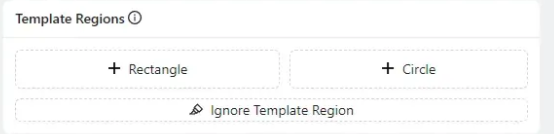
Adding Regions
Click + Rectangle or + Circle in the Template Regions panel to create a new region.
Once placed, you can:
- Click and drag the region to reposition it
- Drag corner handles to resize
- Click the region to access rotation, resize, or delete options
What Makes a Good Template Region
Choose edges that are:
- Simple — clear, well-defined transitions (corners, holes, machined edges)
- Unique — distinctive enough that the pattern won't match random background features
- Consistent — present and identical on every single part that comes through
- Stable — not in areas prone to defects, contamination, or wear
Avoid placing regions on:
- Textured or rough surfaces (too much noise)
- Reflective or shiny areas (inconsistent under different lighting angles)
- Features that may be damaged or missing on defective parts
- Very small details that may be obscured by debris
The Golden Rule: Small and Far Apart
Place 2–3 small template regions as far apart as possible on the part, for example one in the top-left and another in the bottom-right. This is the single most important tip for stable alignment. A single region on one side creates angular jitter (the alignment "wobbles" by 0.5° or more). Two regions on opposite sides average out this error, reducing jitter by an order of magnitude (down to ~0.05°).
You do not need large regions. A small rectangle capturing a sharp corner or a couple of clean holes is far better than a massive region that includes noisy background.
Step 3: Understanding Edge Highlights and the Red Dot
Once you place a Template Region, the Aligner immediately analyzes the edges inside it. You'll see colored highlights overlaid on the image:
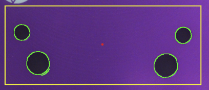
Green Highlights
Green outlines around features mean the Aligner has detected strong, usable edges in that area. These are the patterns the system will use to find and track your part. The more green you see on consistent, stable features, the better your alignment will be.
The Red Dot
The small red dot you see in the center of the template region (or near the center of the image) is the alignment reference point, also called the anchor point or center of alignment. This is the mathematical center that the Aligner uses as the origin for calculating position and rotation offsets.
When the Aligner finds your part in a new image, it calculates how far the part's detected position has shifted relative to this red dot. All ROI positions are then adjusted by the same offset. Think of the red dot as the "pivot point" for the entire alignment transformation.
You don't need to manually adjust the red dot. It is automatically calculated based on your template regions. Having multiple template regions spread across the part gives the system a more stable and accurate reference point.
Red Highlights (Problem Indicator)
If an entire template region shows red highlights instead of green, it means the Aligner could not find enough usable edges in that area. This is a problem — it means the region is not contributing to alignment. To fix this:
- Increase the Sensitivity slider (see Step 5)
- Move the region to an area with sharper, clearer edges
- Improve lighting to increase contrast on the part's features
- Check camera focus — blurry edges won't be detected reliably
Step 4: Clean Up Noise with the Ignore Template Region Tool
Even well-placed regions can pick up unwanted edges: reflections, textures, debris, or background patterns. The Ignore Template Region tool lets you paint over these noisy areas to erase them from the alignment pattern.
- Click Ignore Template Region in the Template Regions panel
- A brush tool activates — paint over any edges you want to remove
- The painted areas turn into a mask that permanently excludes those edges from the alignment pattern
![]()
Why This Matters
The Ignore tool is one of the most overlooked and most important steps in aligner configuration. Every unwanted edge in your template is noise that the Aligner tries to match. If that noise isn't present on the next part (because it was a reflection or a random scratch), the Aligner's confidence drops, or worse, it matches to the wrong location.
Use a high sensitivity + aggressive cleanup strategy: crank the Sensitivity slider up to detect more edges, then ruthlessly use the Ignore tool to remove every edge that isn't a clean, repeatable part feature. This gives you the best of both worlds — you capture subtle but important edges while filtering out all the noise.
Common things to ignore:
- Shiny spots or glare reflections
- Background textures visible around the part
- Surface textures on the part itself (brushed metal, molded patterns)
- Edges from debris, oil residue, or contamination
- Edges from labels, stickers, or markings that vary between parts
Step 5: Adjust Sensitivity
The Sensitivity slider controls how aggressive the edge-detection algorithm is. Higher values detect more edges (including subtle ones); lower values only pick up the strongest, most obvious edges.

How to find the right setting:
- Start with the default sensitivity
- If your template regions show red highlights (not enough edges), increase sensitivity
- If you see too much green noise on textures and irrelevant features, decrease sensitivity
- The ideal setting is the lowest sensitivity that still gives you solid green highlights on the features you care about
Higher sensitivity is not always better. More edges means more potential for noise. The optimal approach is: increase sensitivity to pick up the edges you need, then use the Ignore tool to remove everything you don't need. This gives you a clean, reliable pattern.
Step 6: Set the Rotation Range
The Rotation Range defines how much rotational variation the Aligner will tolerate when searching for the part.
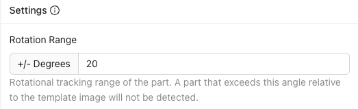
- +/- 180 degrees — Find the part at any rotation (maximum flexibility). Use this for parts on conveyors or robotic pick-and-place systems where orientation is unpredictable.
- +/- 5–20 degrees — For parts that are roughly positioned but may have small rotational variation. Common for fixtured setups with some play.
- +/- 0 degrees — Only match parts that are at the exact same angle as the template. Fastest processing.
Use rotation range as a quality gate. If you set the range to ±10° and a part arrives rotated 15°, the Aligner will fail to find it and you can use that failure as a reject signal. This is a powerful way to catch parts that are incorrectly presented before the AI even runs.
A common mistake is leaving the default rotation range at ±20° when parts can actually arrive at any angle. If your parts can spin freely (e.g., on a vibrating bowl feeder or a conveyor without a guide rail), set it to ±180°. Otherwise, the Aligner will fail on any part rotated beyond ±20° and you'll spend hours debugging what looks like random alignment failures.
Processing speed trade-off: Wider rotation ranges mean the Aligner has to search more orientations, which takes longer. For high-speed inspection, use the narrowest range that covers your actual part variation.
Step 7: Set the Confidence Threshold
The Confidence Threshold is the minimum match quality the Aligner requires before accepting a detection as valid.

- Range: 0.0 to 1.0 (lower percentage = stricter match, 1% indicates an identical match)
- Recommended: 0.6 – 0.9 for most applications
How confidence works:
The Aligner calculates a correlation score between the edge pattern in the template and the edges it finds in the new image. This score factors in pattern similarity, spatial accuracy, and edge quality. If the score exceeds your threshold, the alignment is accepted. If not, it's flagged as a failure.
Tuning guidelines:
| Symptom | Action |
|---|---|
| Aligner matches to wrong objects or background | Increase threshold (try 0.85–0.95) |
| Valid parts are not being detected | Decrease threshold (try 0.60–0.70) |
| Alignment works on most parts but fails on a few | Check if failing parts have obscured features, then adjust |
Step 8: Enable Scale Invariant (When Needed)
The Scale Invariant toggle allows the Aligner to detect parts that appear slightly larger or smaller than the template, handling ±10% size variation. This compensates for parts being slightly closer to or farther from the camera.
Enable Scale Invariant when:
- Parts are on a conveyor that may ride higher or lower
- Parts are presented by a robot that doesn't guarantee exact Z-height
- Your fixture has play in the vertical axis
- Part thickness varies and affects apparent size in the image
Leave it disabled when:
- Parts are at a consistent distance from the camera
- You want maximum alignment speed (scale search adds processing time)
- Size variation would actually indicate a problem (wrong part)
Step 9: Save and Test with Live Preview
Once you've configured your template regions and settings:
- Click Save at the bottom of the settings panel. This trains and deploys the Aligner model.
- Toggle Live Preview Mode (the "Live" button at the top of the page).
- The preview pane switches from the static template to the live camera feed, with alignment applied in real-time.
Validation Checklist
With Live Preview active, physically test the alignment:
- Move the part left, right, up, down — ROIs should follow smoothly
- Rotate the part within your specified range — ROIs should rotate with it
- Try the edges of the range — what happens at ±max rotation?
- Present a different (but valid) part — does alignment still hold?
- Try to break it — put the part at extreme positions, partially occlude features, add debris near template regions
Always try to break the alignment before moving on. If the alignment is fragile, it will fail unpredictably in production. Spend 2–3 minutes actively trying to cause a failure. If it survives your testing, it's ready for production. If not, fix it now. Don't proceed to ROI configuration and AI training, or you'll have to redo everything when alignment problems surface later (waterfall effect).
Tips and Tricks
Align to Edges That Never Change
The most common aligner mistake is placing template regions on features that vary between parts. Even small differences (a slightly different label position, a screw that's angled differently, a solder joint that varies) will reduce alignment confidence or cause jitter.
Best features to align to:
- Machined edges, milled slots, drilled holes
- PCB board outlines, mounting holes
- Molded features with tight tolerances (ribs, bosses)
- Stamped part outlines or laser-cut edges
Use Multiple Regions Strategically
Two well-placed regions are better than five poorly-placed ones. The ideal setup:
- Region 1: Top-left (or top) of the part — clear corner or hole
- Region 2: Bottom-right (or bottom) of the part — different distinctive feature
This triangulation gives the Aligner both position and rotation data with maximum baseline distance, minimizing angular error.
When the Aligner Can't Find the Part
If alignment consistently fails:
- Check the confidence value in Live Preview — is it close to your threshold or near zero?
- If near zero: your template regions have no usable features — redesign them
- If close to threshold: lower the threshold slightly, or clean up noisy edges with the Ignore tool
- If it works on some parts but not others: the varying parts likely have obscured or missing features where your template regions are placed
Speed Optimization
For high-throughput applications where milliseconds matter:
- Use 2 regions (not 4+) with clean edges
- Set the narrowest rotation range that covers your actual variation
- Set Sensitivity to the minimum that gives solid green edges
- Disable Scale Invariant if your Z-distance doesn't change
- Keep template regions small — large regions mean more edges to process
Recovering from Upstream Changes
If you change any of the following, you must redo the Aligner setup:
| Change Made | What to Redo |
|---|---|
| Lens distortion correction | Recapture template, redo all regions |
| Camera lens or focal length | Recapture template, redo all regions |
| Camera mounting position | Recapture template, possibly redo regions |
| Lighting configuration | Recapture template, verify edges still detected |
| Image exposure/gain settings | Recapture template, verify edges still detected |
When to Skip the Aligner
Not every application needs alignment. Disable the Aligner (check "Skip Aligner") when:
- Parts are in a precision fixture that guarantees position within 1–2 pixels
- Parts are mechanically registered with zero play
- You need maximum processing speed and position variation is negligible
- You're using a segmenter with location-invariant properties for 3D part variation
When the Aligner is skipped, ROIs stay at their fixed positions on the template image. The system skips the alignment computation entirely, which is faster but requires perfectly consistent part presentation.
Quick Reference: Aligner Settings
| Setting | Purpose | Recommended Range | When to Adjust |
|---|---|---|---|
| Sensitivity | Edge detection aggressiveness | Lowest that gives green edges | Red highlights in regions: increase |
| Rotation Range | Max rotational tolerance (±degrees) | Match your actual part variation | Parts arriving at unexpected angles |
| Confidence Threshold | Minimum match quality for valid alignment | 0.6 – 0.9 | False matches: increase; missed parts: decrease |
| Scale Invariant | Allow ±10% size variation | Enable only when Z-distance varies | Parts at varying camera distance |
Troubleshooting Quick Reference
| Problem | Likely Cause | Fix |
|---|---|---|
| ROIs don't move at all | Skip Aligner is enabled, or no template regions exist | Disable Skip Aligner; add template regions |
| Confidence always near 0% | Template regions have no usable edges | Move regions to areas with strong, clean edges |
| Alignment jitters/wobbles | Single region or regions placed too close together | Add regions far apart on opposite sides of the part |
| Matches wrong object | Patterns not unique enough, threshold too low | Add more regions with distinctive features; increase threshold |
| Works on some parts, fails on others | Template regions on variable features | Move regions to features present on ALL parts |
| Alignment is slow | Too many regions, wide rotation range, Scale Invariant on | Reduce to 2 regions, narrow rotation range, disable scale if not needed |
Related Articles: